Lesson No 07. Waves Optics
Introduction
We have studied in class XI that light travels in a straight line which was considered to be in the form of ray.In the form of ray light shows various phenomenon like Reflection,Refraction,Dispersion. In previous class we have studied about reflection of light through spherical mirrors and refraction through lens and many more thing about optical instruments. In this chapter we are going to discuss about Propagation of light in surrounding ,its various properties in the form of a waves.
___________________________________________________________________________________
Various theory related to light
Earlier we studied light to be in the form of ray which travels in straight line i.e One -dimensional Motion.The shadows,images were the result of light having linear motion. based on this ray R Discartes s studied particle nature of light which was further proposed by Newton in 1636.
Newton's Corpuscular Theory
- Every light source emits large number of minute particles which was termed as 'corpuscles'that travels in a straight line without any external force.
- This particle was elastic,rigid,massless and travels with high speed which vary from medium to medium.
- The different size of the corpuscles corresponds to different colour of light.
- When this particle fall on our retina its creates sensation of light.
This theory could satisfactorily expain reflection,refraction and inverse square law but had some drawbacks:
- Partial reflection and refraction was not explained by this theory
- this theory predicted that speed of light in denser medium is larger than rarer medium which was proved wrong by Focault.
___________________________________________________________________________________
Wave theory of Light
- The wave theory was proposed by Dutch scientist Christian Huygens in 1678.
- Light travels in form of waves(longitudinal) which travels with uniform velocity in homogenous medium.
- This light wave was due to vibration of the particles of the medium.
- As propagation of longitudinal waves required medium to travel ,so Huygen suggested there exist a hypothetical medium called 'luminiferous ether' which is available in vaccum medium.
___________________________________________________________________________________
Wave front and Wave Normal
A locus of all point of a medium to which waves reaches simultaneously so that all the point are in the same phase is called wavefront.
A perpendicular drawn to the surface of a wavefront at any point of a wavefront in direction of propagation of light is called wave normal.
___________________________________________________________________________________
Huygen' s Principle
- Every point on a wavefront act as a secondary waves in all direction wherever possible.
- Every point on new secondary waveform creates new wavelets in forward direction.
- The resultant wavefront is given by the tangent to all the secondary wavelets at that instant.
___________________________________________________________________________________
Construction of spherical wavefront
Let AB is a cross section of a spherical wavefront from a point source (S)
Let X,Y,Z be the point on wavefront AB. Now they behave as a secondary source and start sending secondary wavelets in forward direction according to Huygen's Principle.Let this system is in air medium hence speed of light is 'c' and thus this wave cover a distance of ct in time 't'. Now common tangent to the wave with centre X,Y,Z gives the new wavefront A' B' after time 't'.
Construction of Plain wavefront
Let AB be the plain wavefront due to point source (S) called as primary wavefront.Let M,N,O,P on wavefront AB which act as a secondary source and start sending secondary wavelets in forward direction according to Huygen's Principle.Let this system is in air medium hence speed of light is 'c' and thus this wave cover a distance of ct in time 't'. Now common tangent to the wave with centre M,N,O,P gives the new wavefront A' B' after time 't'.
___________________________________________________________________________________
Reflection of a light wave on a plane surface
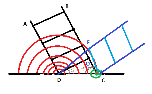
To understand reflection of light on a plane surface in form of wave, let us consider wavefront AB incident on a plane surface making an angle 'i' with surface as shown in below figure.
In this figure, when wavenormal A is at point D, then wave B reaches at point O.As the both wave is in same medium their velocity is same. Let the velocity of wave is 'v' . After incident on the surface at D the wave startt forming next waveform in the same medium in forward direction and reaches point F in time 't' covering a distance DF= 'vt' and on the same time the wave at point O moves in forward direction and reaches point C covering a distance of OC = 'vt' in time 't' .
As wave travel in same medium thus distance covered by wave is given by DF = OC = vt.
Now according to huygens principle , the common tangent FC gives the next wave and thus reflection takes place.
Now In triangle DFC and Triangle DOC,
DC = DC --------------( Common side)
DF = OC ( Distance tarvelled in same time)
Angle DFC = Angle DOC --------( each 90)
thus Triangle DFC ∽ Triangle DOC
Angle ODC = Angle OCD -------(corresponding angle)
Angle i = Angle r
When reflection take place Angle i = Angle r
___________________________________________________________________________________
Interference of a light wave
In previous topic we have learned reflection of a light in form of wave which was explained by Huygens' . If the light propagates as waves then it must exhibit interference effect in medium of propagation . Thus in 1801 ,Thomos Young performed his experiment and demonstrated interference of light.
The modification in the intensity of light produced by bthe superposition of two or more light wave s is called interference of light
If two or more light passes through a medium , and interfere with each other, then the resultant light has intensity which is governed by Principle of Superposition of wave.
Superposition of Wave
When to or more waves overlap, the resultant displacement at any point and at any instant is equal to the vector sum of instantaneous displacements that would be produced at the point by individual waves if each wave is present alone.
From the above figure, there are two light source A and B emitting waves in forward direction .These circular waves travel out in form of trough and crests .Let continuous lines represent the crest and dotted lines represent troughs. The points at which a crest falls upon crest and a trough an trough are marked by (x) crosses . At such points the resultant displacement is maximum , the waves interfere is called constructive interference.
While other points where a crest falls upon a trough and trough falls on crest are marked as (0).These are the points on the surface and the resultant is zero and the resultant effect at these point is called destructive interference.
___________________________________________________________________________________
Condition for interference
Consider two source of light P and Q as shown in fig below, Both the source at very close to each other.
Both the source is emitting light in forward direction having wavelength λ and having same frequency . At point O both wave reaches at same time without any phase difference. Hence they will produce constructive interference and the point O will be bright. In this case both wave travels equal distance and path difference (QR - PR) is zero.
Constructive Interference
Consider a point R on the screen. The path difference between both wave at R is (QR-PR) .The point R will be bright if both wave arrive at point R with
phase difference of : 0 , 2π , 4π, 6π,-----------nπ
or
path difference is 0,2 λ /2 , 4λ /2 , 6λ/2--------------2n (λ/2)
i.e even multiple of λ/2
Destructive Interference
If both wave reaching at point R is having a phase difference out of phase they will produce destructive interference. The point R will be dark when
Phase difference is π , 3π, 5π-------(2n-1)π .
Path difference is λ /2 , 3λ /2 ,5λ /2 ,-----------(2n-1)λ /2
i.e odd multiple of λ /2
___________________________________________________________________________________
Young Double slit experiment
Mathematical Approach of Youngs double slit experiment

Let two light source S1 and S2 are narrow parallel slit sepearated by a distance 'd' emitted from Source S. The wave from Both slit behave as it is emerging from S1 and S2.They travel in same medium and reaches at screen which is situated at a distance of D from slit source.
Let Point O is at equidistance from point S1 and S2 in same phase .Hence the point O will be Bright called as central bright. Now let R be any point at a distance 'x' from O . the path difference between the waves reaching R from S1 and S2 is (S1R - S2R) . Thus from figure above, Triangle S1MR and Triangle S2NR is right angled triangle.
Applying phythagoras theorem in S1MR ,
___________________________________________________________________________________
Fringe width
The distance between the center of two adjacent bright or dark bands is called as fringe width.
Fringe width of bright Bands: Let us consider two adjacent bright frindge at a distance xn and xn+1 from Central Bright. Then according to Youngs experiment,
xn = (nλD)/d----------(1)
xn+1 =((n+1)λD)/d) ---------------(2)
xn+1 - xn =((n+1) λD)/d) – (nλD)/d)
xn+1 - xn =(n+1-n) λD)/d
xn+1 - xn = (λD)/d
Fringe width of Dark Bands: Let us consider two adjacent Dark frindge at a distance xm and xm+1 from Central Bright. Then according to Youngs experiment,
xm = ((2m-1) λD)/2d----------(1)
xm+1 =(2(m+1-1) λD)/2d)-----------(2)
xm+1 - xm = (2(m+1)-1-2m+1) λD/2d)
xm+1 - xm = (λD)/d
___________________________________________________________________________________
Condition for Obtaining sharp Interference Pattern
The conditions required for steady interference pattern are as follows:
There should be two source of light and that should be:
- Coherent, i.e, light wave should have no phase difference. Both the source should be obtained from a single source.
- Monochromatic light is necessary, i.e light should have same frequency , colour of light should be same.
- Equal amplitudes .i.e light wave should have same amplitide of vibrations
- Narrow sources. Point sources of light in the form of illuminated slits can be used.
- distance between both slit should be as close as possible.
- The distance from source to screen should be large. should be close to each other.
- Should emit waves in nearly the same direction.
___________________________________________________________________________________
Fresnel Biprism experiment for obtaining wavelength
Biprism is a two identical joined prism (base) having refracting angle of approx 1 degree.
initially the slit, biprism and eyepiece are kept at same height so that their centre get in same line.When refracting edge of biprism is adjusted such that it get parallel to slit, interference pattern is obtained.
Thus we can determine wavelength by using Formula ,
X = λD/d or λ= Xd/D
The distance between source and screen can be easily obtained by measuring using scale on optical bench.
Now the width W is measured using eyepiece . The micrometer reading is noted by adjusting cross wire at centre of brigth fringe and then it is moved horizontally over N fringes which is known.Thus difference of two reading gives the actual length xand calculation is done as follow:
W= x/N
The distance d cannot be obtained directly as the source is virtual. Thus conjucate foci method is used.
Conjucate foci method: In this method a convex lens of short focal length is introduced between biprism and eyepiece.Now the lens is moved towards the slit and its length L1 is so adjusted that sharp image AB is obtained and calculation is done as shown below
Size of image = Distance of image
Size of object Distance of object
d1/d = v/u -----------(1)
.Now the lens is moved towards the eyepiece and its length L2 is so adjusted that sharp image PQ is obtained and calculation is done as shown below
Size of image = Distance of image
Size of object Distance of object
d2/d = u/v -----------(2)
From 1 and 2
(d1 x d2)/ d2 = 1
d = √d1 x√d2
___________________________________________________________________________________
Intensity Distribution
Consider two wave ,
Equation for each wave is given by,

Let I1 and I2 are the intensities of two interfering waves, then
___________________________________________________________________________________
Diffraction of Light
The Bending of light near the edge of an obstacle or slit and spreading in shadow region towards the obstacle is called Diffraction.
The border that is seen around the mountain just before sun rises behind it is a phenomenon of diffraction of light.
Diffraction of lazer beam
Diffraction in nature
There diffraction is categorized into two types :
a) Fresnel Diffraction : In this case , the screen is at a finite distance from source and the waveform is considered spherical or cylindrical
b) Fresnel Diffraction : In this case, the screen and the source is at a infinite distance and wavefront is considered as plane wavefront.
___________________________________________________________________________________
Experimental observation
From above experiment consider a monochromatic light of wavelength λ is incident on a slit XY having width 'a' . Now when the light travelling from X reaches O and light travelling from Y reaches O with no difference in path , the point obtained is central bright with maximum intensity. This light wave are in same phase, it is the brightest band in diffraction pattern.
Position of secondary minimum( dark band)
Now, consider a point P at a distance of 'm' from central bright 'O'. The wave from X reaches at P and wave from Y reaches at P having some phase difference. The point p will be dark or bright depends upon the path difference NY between the two i.e XP and YP.
From Triangle XYN,
Sinɵ = YN /XY
Sinɵ = YN / a
YN = asinɵ -----------(1)
If path difference is equal to λ , which is equal to wavelength of light, then point P will be dark. The wave front can be considered two half each i.e XC and YC . Thus if path difference between XY is λ thenpath difference between two halves between XC and YC will be λ/2 . For every point from XC there will be Corresponding Point YC with phase difference of λ/2 . Thus destructive superposition occurs and point is a dark point.
from (1)
asinɵ = nλ
a (OP/CP) = nλ
a m/D = nλ
m = nλD / a
Position of secondary maximum( bright band)
From equation (1)
asinɵ = (2n+1)λ/2
a (OP/CP) = (2n+1)λ/2
a m/D = (2n+1)λ/2
m = (2n+1)λD /2 a
Thus diffraction pattern is a central bright followed by altrenate dark and bright band on both side.
The width of Central Maxima = 2m
= 2 λD/a


Thnx sir
ReplyDeleteThnx
ReplyDeleteThank you sir
ReplyDelete